
Abstract
Energy consumption of felt conditioning is about 30 % compared to the whole vacuum system of the paper mill, and specific energy consumption (SEC) is 20 - 30 kWh/tn. Estimated electric energy costs of felt conditioning are 1.0 - 2.0 €/tn, thus it is important to be sure this amount of money and energy is used in the optimal way.
A method for benchmarking and estimating the efficiency of uhleboxes is presented in this article. Felt moisture level, dewatering and operation conditions are compared to the typical running data of felts.
Corresponding application can be downloaded from KGU AppStore free of charge.
For details, please compare to: http://www.kgu.fi/downloads.html
1. General
Even though it is difficult to describe the efficiency of uhleboxes with simple mathematical models, we concluded, that a simple benchmarking method was needed to evaluate the operation of felt conditioning.
Traditionally similar boxes have been selected to all felts of the press section, even though capacity requirements can vary significantly at different positions. Felts, have also developed during the years, thus sometimes it can happen, that even at the same machine some felts are running too wet, while the other ones are running dry.
Felt aging has also a strong effect on the operation of the felt, thus modeling methods can never be very exact. Energy consumption of felt conditioning is anyhow so high, thus it is important to be able to estimate efficiency, even with a rough method.
We made a simple application (Excel file), which can be downloaded from the KGU Appstore "Efficiency of uhleboxes". In the following we will show how to use this application, and with a simple example explain how conclusions can, or can not, be made based on it. The theory and development of the model is described in more detail at our earlier blog (published in Feb, 2014 ).
2. PM production data
In our example we study the operation of felt conditioning an a two ply liner machine. Press section has two nips, shoe at the first nip. As input data, the application needs PM production data and web moisture before and after press section. For details, see picture 1.
Total removed water amount is calculated based on the production data. It can be used to verify the felt moisture measurements and estimate the ratio of nip and uhlebox dewatering. Today many new machines have water measurements, but most older machines do not.
 |
| Picture 1: PM production data needed at the application |
Total removed water amount is calculated based on the production data. It can be used to verify the felt moisture measurements and estimate the ratio of nip and uhlebox dewatering. Today many new machines have water measurements, but most older machines do not.
3. Moisture measurements of felts
Felt moisture measurements are also needed to estimate the efficiency of felt conditioning, as well as felt dry basis weight and uhlebox operation conditions. Compare to picture 2.
Felt measurements typically include more information of moisture profiles and permeability of felts, but in this application we need only average moisture before and after nip ( = after and before ulhebox). Dry felt basis weight is needed to calculate the relative moisture.
In can often be seen, that the uhlebox vacuum is shown and commented at felt measurement reports, but uhlebox slot widths are not commented at all. However open area of the box is as important as vacuum level, and at typical operation conditions they more or less compensate each other ( = 10 % increase in the vacuum level equals 10 % bigger open area).
As an example, one Middle European mill had overloading problem at vacuum system. This problem could not be solved with a desktop study, thus mill visit was needed. During the visit It was noticed, that PU felt and 3rd press felt piping were cross-connected. The big pump of PU felt was connected to the 3rd press felt, where open area of the box was only half compared to the PU felt. Vacuum level control did not exist, thus vacuum level was very high ( most of the time over 65 kPa) and that's why the motor was overloaded. Luckily felt conditioning was so much "over-sized" , that required felt moisture could be achieved, and only the motor overload was an issue for the mill.
 |
| Picture 2: Required data for the estimation of dewatering efficiency of uhleboxes. |
Felt measurements typically include more information of moisture profiles and permeability of felts, but in this application we need only average moisture before and after nip ( = after and before ulhebox). Dry felt basis weight is needed to calculate the relative moisture.
In can often be seen, that the uhlebox vacuum is shown and commented at felt measurement reports, but uhlebox slot widths are not commented at all. However open area of the box is as important as vacuum level, and at typical operation conditions they more or less compensate each other ( = 10 % increase in the vacuum level equals 10 % bigger open area).
As an example, one Middle European mill had overloading problem at vacuum system. This problem could not be solved with a desktop study, thus mill visit was needed. During the visit It was noticed, that PU felt and 3rd press felt piping were cross-connected. The big pump of PU felt was connected to the 3rd press felt, where open area of the box was only half compared to the PU felt. Vacuum level control did not exist, thus vacuum level was very high ( most of the time over 65 kPa) and that's why the motor was overloaded. Luckily felt conditioning was so much "over-sized" , that required felt moisture could be achieved, and only the motor overload was an issue for the mill.
4. Water balance of felt.
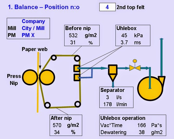
Based on the data given at pictures 1 and 2, water balance of the felt can be calculated (Compare to picture 3).
Water content of the felt, relative moisture and uhlebox operation conditions can be seen from the water balance of the felt. The operation values of one felt can be seen at a time, and the felt can be selected at the right top corner of the picture.
The product of vacuum (kPa) and retention time (ms) correlates directly with the energy consumption of the vacuum pump or blower. Thus, it is logical, that felt moisture also depends on the product of vacuum level and retention time ( = slot width) of the box. Uhlebox dewatering and vacuum*time are shown at the bottom of the balance sheet.
 |
| Picture 3: Felt water balance ( 2nd nip top felt) |
Water content of the felt, relative moisture and uhlebox operation conditions can be seen from the water balance of the felt. The operation values of one felt can be seen at a time, and the felt can be selected at the right top corner of the picture.
The product of vacuum (kPa) and retention time (ms) correlates directly with the energy consumption of the vacuum pump or blower. Thus, it is logical, that felt moisture also depends on the product of vacuum level and retention time ( = slot width) of the box. Uhlebox dewatering and vacuum*time are shown at the bottom of the balance sheet.
5. Benchmarking of uhlebox efficiency
When the uhlebox dewatering is plotted as function of felt moisture before the box ( = after nip), we can benchmark the operation conditions of each felt.
In our example, we selected a machine, where the operation conditions of felts differ from each other, and thus the conclusions are easier to do.
Red dot in the graph indicates the felt, which is shown at the water balance ( = 2nd top felt).
In this kind of press section concept, the first nip removes most of the water. Thus relatively small amount of water is available at the 2nd nip. Compared to the required dewatering at the uhlebox, a lot of energy is used at the 2nd nip top felt. As a result of this, felt is running dry.
On the other hand, operation conditions of the 1st bottom felt are totally different. Compare also to picture 5.
The 1st nip of the PM is equipped with shoe and thus dewatering at the nip is high. For some unknown reason, the slot width of uhleboxes of 1st bottom felt felt were small compared to the other felts. As a result of it, felt was running wet, and caused operation problems at the PM.
PU felt and 2nd nip bottom felts in this example are at the middle area, and no clear conclusions could be made.
In this example, differences were clear, and conclusions easy to do. However, the mill had been operating in the same way for ever. Thus, even if this method seems simple, it is sometimes important to list all basic operation parameters, and check if there exists easy improvement possibilities. In this case the solution was to change the uhleboxes between 1st bottom and 2nd top felt, and modify vacuum system capacity correspondingly.
This application (3.5 Efficiency of felt conditioning) can be loaded free of charge from our homepage ( http://www.kgu.fi/downloads.html ).
This method of benchmarking the felt conditioning is simple, but it gives us (process engineers) a simple method to estimate vacuum requirements at the different PM concepts, and we hope it could be useful for the paper makers also.
 |
| Picture 4: Dewatering efficiency of uhlebox (benchmarking). |
In our example, we selected a machine, where the operation conditions of felts differ from each other, and thus the conclusions are easier to do.
Red dot in the graph indicates the felt, which is shown at the water balance ( = 2nd top felt).
In this kind of press section concept, the first nip removes most of the water. Thus relatively small amount of water is available at the 2nd nip. Compared to the required dewatering at the uhlebox, a lot of energy is used at the 2nd nip top felt. As a result of this, felt is running dry.
On the other hand, operation conditions of the 1st bottom felt are totally different. Compare also to picture 5.
 |
| Picture 5: Operation conditions of 1st bottom felt |
The 1st nip of the PM is equipped with shoe and thus dewatering at the nip is high. For some unknown reason, the slot width of uhleboxes of 1st bottom felt felt were small compared to the other felts. As a result of it, felt was running wet, and caused operation problems at the PM.
PU felt and 2nd nip bottom felts in this example are at the middle area, and no clear conclusions could be made.
In this example, differences were clear, and conclusions easy to do. However, the mill had been operating in the same way for ever. Thus, even if this method seems simple, it is sometimes important to list all basic operation parameters, and check if there exists easy improvement possibilities. In this case the solution was to change the uhleboxes between 1st bottom and 2nd top felt, and modify vacuum system capacity correspondingly.
6. More examples
The previous example was from the other side of Atlantic ocean. Attached two more examples, one from Scandinavia, and the other one from Far East.
The conclusions of these examples can be explained based on picture 6 ( compare to blog Feb 2014). When energy consumption at the uhlebox is increased ( = higher vacuum and / or higher air flow and retention time), felt moisture decreases. However, the curve "saturates" when relative moisture of the felt is low enough, and the moisture content can not be decreased, no matter how much energy is used. In this example the curve becomes "flat" when Vacuum*time is over 100 - 120 Pa*s, and felt moisture about 650 g/m2.
As an example, one Scandinavian mill wanted to improve the efficiency of uhleboxes. Felt was running wet, and according to benchmarking the operation point was near the red line at picture 7 ( = blue dot). Open area of the uhlebox was increased, but unfortunately it was connected to a vacuum pump ( "Nash pump"). Vacuum level control did not exist, thus vacuum level dropped and felt dryness did not improve.
Another example is from Far East, where mill also wanted to improve dewatering at the uhleboxes of PU and 1st bottom felt. Red dot at picture 7 indicates the operation point of the felts. Increase of vacuum level could however have only marginal effect to the felt moisture content, because the felt moisture content was already low ( = operation was at the "saturated flat area"). Compare to picture 6.
So far we have been talking about uhlebox dewatering only. Minimizing felt moisture before nip is however not necessarily the optimum operating strategy. Important is to maximize total water removal including also dewatering at the nip.
The conclusions of these examples can be explained based on picture 6 ( compare to blog Feb 2014). When energy consumption at the uhlebox is increased ( = higher vacuum and / or higher air flow and retention time), felt moisture decreases. However, the curve "saturates" when relative moisture of the felt is low enough, and the moisture content can not be decreased, no matter how much energy is used. In this example the curve becomes "flat" when Vacuum*time is over 100 - 120 Pa*s, and felt moisture about 650 g/m2.
 |
| Picture 6: Development of felt moisture |
As an example, one Scandinavian mill wanted to improve the efficiency of uhleboxes. Felt was running wet, and according to benchmarking the operation point was near the red line at picture 7 ( = blue dot). Open area of the uhlebox was increased, but unfortunately it was connected to a vacuum pump ( "Nash pump"). Vacuum level control did not exist, thus vacuum level dropped and felt dryness did not improve.
 |
| Picture 7: Benchmarking of felt Runing conditions |
Another example is from Far East, where mill also wanted to improve dewatering at the uhleboxes of PU and 1st bottom felt. Red dot at picture 7 indicates the operation point of the felts. Increase of vacuum level could however have only marginal effect to the felt moisture content, because the felt moisture content was already low ( = operation was at the "saturated flat area"). Compare to picture 6.
So far we have been talking about uhlebox dewatering only. Minimizing felt moisture before nip is however not necessarily the optimum operating strategy. Important is to maximize total water removal including also dewatering at the nip.
7. Dewatering at the nip
Especially with printing and writing papers ( and also with lower basis weight boards) significant part of the water is removed at the nip. In these machines purpose of the uhlebox ( if used at all) is to equalize moisture profiles, condition the felts and control felt moisture before the nip to the targeted level.
When nip dewatering is targeted, it is important to avoid over-drying of the felt. Felt suppliers should be able to inform, what is the optimum moisture for different felt types. It depends on the felt type and age, and sometimes even felt moisturizing showers have been used to speed up the start of the felt. Compare also to picture 8.

Picture 8: Examples of operation conditions when
nip dewatering is targeted
When nip dewatering is targeted, it is important to avoid over-drying of the felt. Felt suppliers should be able to inform, what is the optimum moisture for different felt types. It depends on the felt type and age, and sometimes even felt moisturizing showers have been used to speed up the start of the felt. Compare also to picture 8.
|
| Picture 8: Examples of operation conditions when nip dewatering is targeted |
8. Felt operation summary
Summary of felt running and operation data is displayed end of our application. This table summaries the most important operation parameters of all felts. See picture 9.
 |
| Picture 9: Summary table of felt operation conditions |
9. Conclusions
When the operation of PM vacuum systems are studied, often the target is energy savings, but in many cases different operational issues are also studied. Other articles concerning benchmarking and efficiency losses of PM vacuum systems have been described at earlier blogs, and all applications can be found from our AppStore.This application (3.5 Efficiency of felt conditioning) can be loaded free of charge from our homepage ( http://www.kgu.fi/downloads.html ).
This method of benchmarking the felt conditioning is simple, but it gives us (process engineers) a simple method to estimate vacuum requirements at the different PM concepts, and we hope it could be useful for the paper makers also.
Very educative, Thanks
ReplyDelete